ACI - Adjacent-Channel Interference
How do WiFi channels affect each other? And what can we do about it?
An interesting approach to this problem was published in this article:
Mi, Penghui, and Xianbin Wang. "Improved channel assignment for WLANs by exploiting partially overlapped channels with novel CIR-based user number estimation"
It consists of the following:
1. The coefficient of influence of one channel on another for OFDM signals can be calculated using this formula:
where i and j are the channel numbers, t=5|i-j|[MHz] is the distance between the central frequencies of the channels, Si (F) and Sj (F) distributions of signal power over the frequency range of channels i and j, respectively. These distributions are determined by the spectral masks of the OFDM signals (Fig.1).
The authors define this parameter as the I-factor and provide the normalized results of its calculation in the following graph (Fig. 2).
2. This parameter has a cumulative effect.
To calculate a channel quality, the authors propose the term equivalent to a number of users in a channel:
where C is the set of 802.11 channels, and N(j) is the number of users in a particular channel. This way the channel with the smallest equivalent number of users will be considered the best channel.
The results shown in figure 2 are refined based on the results of experiments. However, we should mention that these indicators are relevant for the case when both the interfering device and the device in question operate in the same bandwidth spectrum of 20 MHz. However, the 802.11 n standard assumes the possibility of using both 20 and 40 MHz (channel bonding). The following publication provides spectral masks for 40 MHz wide signals:
V. Shrivastava, S. Rayanchu, J. Yoon, and S. Banerjee, “802.11n under the microscope”, Internet Measurement Conference ’08, 2008.
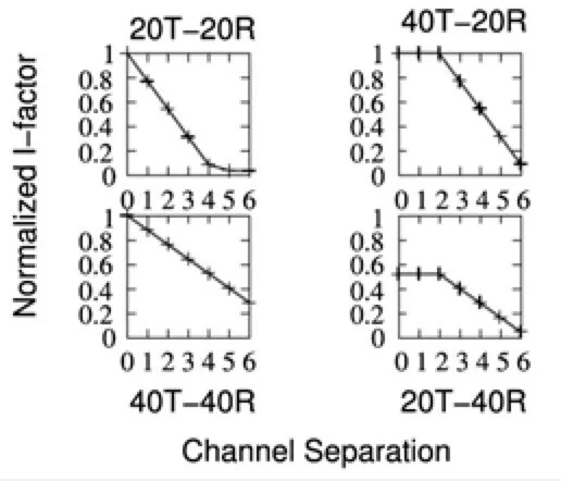
Using these spectral characteristics and the same method as described above in Formula 1, the authors obtain the interference factors for four different cases:
the interfering device and the device in question use signals with a 20 MHz bandwidth (20T-20R)
both use 40 MHz (40T-40R)
the interfering device - 40 MHz, the device in question - 20 MHz (40T-20R)
the interfering device - 20 MHz, the device in question - 40 MHz (20T-40R)
Provided that we are only interested in cases where the device in question occupies 20 MHz (optimal for the 2.4 GHz spectrum), the results can be shown in the following table:
We should mention that the expansion of the spectrum does not occur symmetrically, but rather to the left or to the right side.
For example, if the device was on channel 10 at 20 MHz, then for 40 MHz, channel 10 will be primary, and channel 6 secondary. In this case, there are the following rules for resolving collisions during the multiple access stage:
the primary channel is considered busy if it detects a signal that exceeds the CS (carrier sense) threshold
the secondary channel is considered busy if a signal is detected either on the primary or secondary channel, or on both channels (see 802.11 n 20/40 MHz BSS Mode Rules).
Therefore, it is not possible to consider the mechanism of expanding the spectrum as a mechanism for adding an independent device to the spectrum. That is why it is proposed to review the extended part of the spectrum by considering it as an ACI.
From this series:


