DOCSIS FBC Impairment Algorithms - Adjacency
There are many different Full Band Capture (FBC) impairments - an interesting one is the adjacency impairment, since it is often so pronounced on the spectrum.
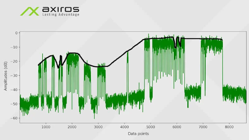
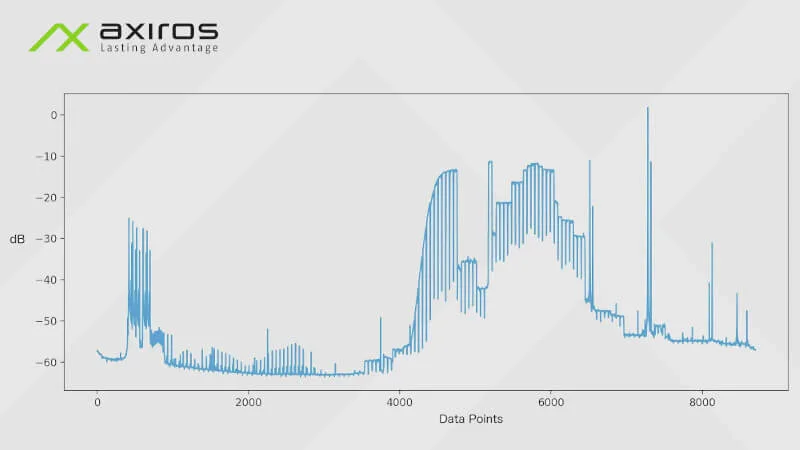
The Figures below shows a small adjacency: The channels suddenly jump slightly in their dB level.
Adjacency Detection
The DOCSIS Proactive Network Maintenance (PNM) paper shows a very good illsturation of an adjacency too. Unfortunately, they are light with further explanations on how to detect one, since there are a few specifics to keep in mind.
First of all, a certain number of channels around a candidate adjacency must be flat, i.e. the channel tilt should be lower than a certain threshold for the majority (>60%) of channels around the two candidate channels that may have an adjacency. For calculating the tilt, an interesting idea could be fitting a linear regression line onto the channel, and taking the slope as the tilt value.
Secondly, between two channels, the power difference should be higher than a certain threshold. The power of a channel is calculated by transforming each amplitude with 10^(amplitude * 0.1), taking the sum over all amplitudes and then transforming back with 10 * log10(sum).
Lastly, if there are gaps between two channels, which often indicate different services (each service has a continuous group of channels that have no gaps in between), no adjacency should be detected. The difference is likely wanted.
There are a few more considerations such as how much to smooth the data beforehand.
Now, this whole procedure in turn requires very good knowledge of all the channels that are contained in the spectrum. For an interesting approach on how to solve this, check out this blog post.
It is very interesting to note that the Federal Communications Commission (FCC) has set the maximum power difference that is allowed at 3 dB. So a good threshold here could be 3 dB - any power difference above that can be deemed an adjacency impairment.
Adjacency Causes
There are multiple causes for adjacency impairments. A very good example is given in the PNM DOCSIS 3.1 Primer: For instance, the downstream spectrum may be combined from different services with different spectra into a continous spectrum. If this combiner is misconfigured, one of those spectra could end up with higher power than the others, which would manifest itself as an adjacency impairment. This would introduce issues for the other services (e.g. one service could be video → this would introduce buffering and packet loss). An example on how these combiners may look like can be found here.
Often, adjacency impairments may arise very far up the downstream path, thus potentially affecting a lot of customers. For instance, the example in the Primer shows that such issues may already arise before an Optical Transmitter. Optical Transmitters sit between the headend and acess network, after the CMTS, and a CMTS may have thousands of CPEs that it handles.
To keep track of adjacencies in a whole hybrid fiber coaxial (HFC) network, full band capture has be done for each CPE in the network in a certain interval. This results in huge datasets that need to be handled smartly. However, since an adjacency impairment may affect a lot of customers, it is quite an important impairment to detect, and thus it could be worth it to keep track of adjacencies across the network.
This wraps up the post. More posts for other FBC impairments will follow.
* Figures do not represent an actual product, and are shown for illustration purposes.
From this blog series:


